Problems
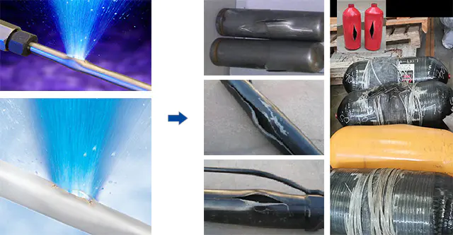
The pressure test cabin is a device that plays an important role in the high pressure test process. The hydraulic pressure is very high up to 690MPa, and the gas pressure is up to 480MPa, when pressure test, blasting and fatigue tests are carried out on pipes (hard pipes, hoses), gas cylinders, casings and cylinders, valve parts, petroleum equipment, fire-fighting tools, etc. The higher the pressure, the larger the size of the pressure test device, and the greater the destructive force is during the test. Therefore, when performing stress testing, not only the accuracy and reliability of the test data are required, but also the safety and controllability of the test are required.
Put forward a plan and discuss it.
The project team mainly focuses on the design and the selection and composition of each functional module of the remote automatic control, pressure test monitoring system, protective cabin safety hazard, alarm system, hydraulic unit, and discuss the proposals.
Technical Design Characteristics
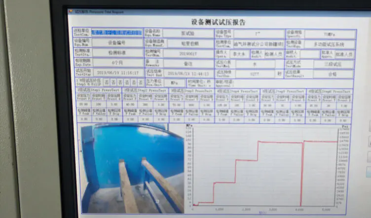
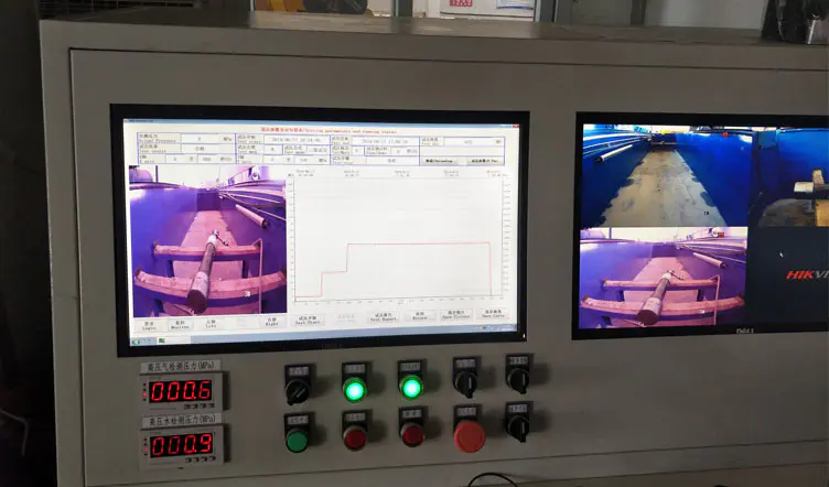
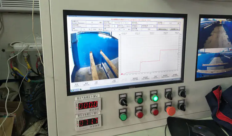
① Pressure test monitoring system: The controllable PTZ camera in the pressure protection cabin can not only rotate 360° through the control handle, but also can move freely along the axis, realizing all-round and real-time monitoring of the camera.
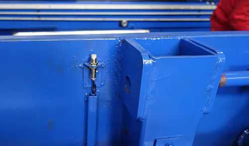
② Install the necessary limit switch, grating protector and locking mechanism in the test pressure protection compartment to ensure that the operator does not misuse during the assembly phase. The pressure test protection compartment has an automatic locking function.
During the pressure test, the door can be opened and closed by a manual pump even in the event of a malfunction of the device.
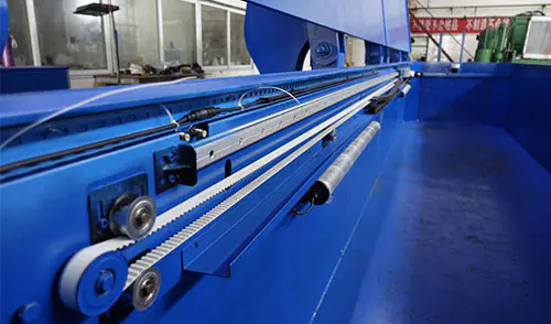
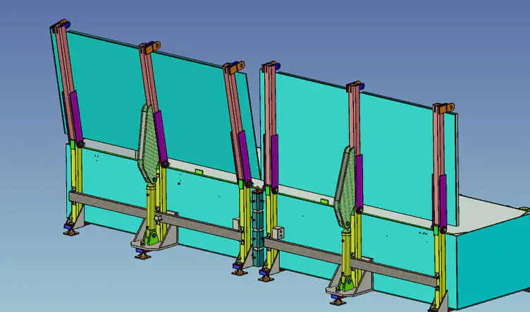
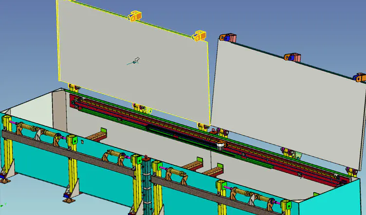
③ For easy transportation, and the user can lengthen the protection cabin as needed, the protection cabin is designed in the form of module structure.
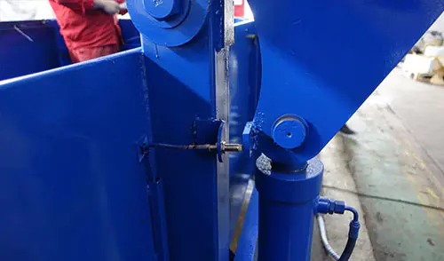
④ The interlocking technology is adopted between the protective door and the test system. When the pressure in the system is not completely relieved to zero, the protective door cannot be opened to avoid accidents.
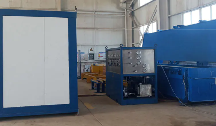
⑤ The hydraulic unit has an automatic temperature control system, which means when the temperature of the hydraulic oil is too high, the cooling system is started, and when the ambient temperature is too low, the heating system is started. Additionally, a liquid level controller, a temperature controller and a pressure transmitter are installed in the fuel tank, and the operating parameters of the fuel tank can be monitored in real time.
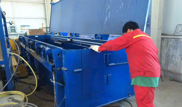
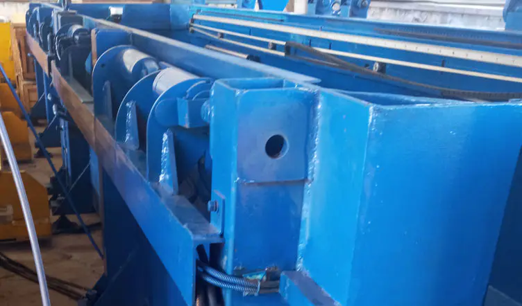
Field Installation and Debugging