
Customer’s Request:
The derivatized gas can be pressurized to 30bar only, which does not meet the requirement of gas delivery.
Solution:
Apply hydraulic booster pump to pressurize the derivatized gas up to 70bar.
Customer’s new request:
- The environment temperature is very high and need heat exchange on compressed gas.
- The high pressure boosted gas is used as a power to bring the gas in the main pipe far.
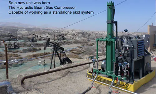
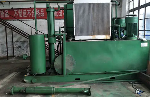
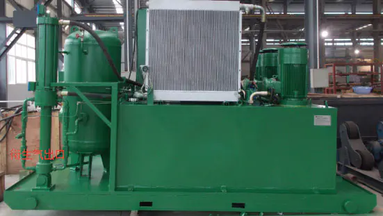
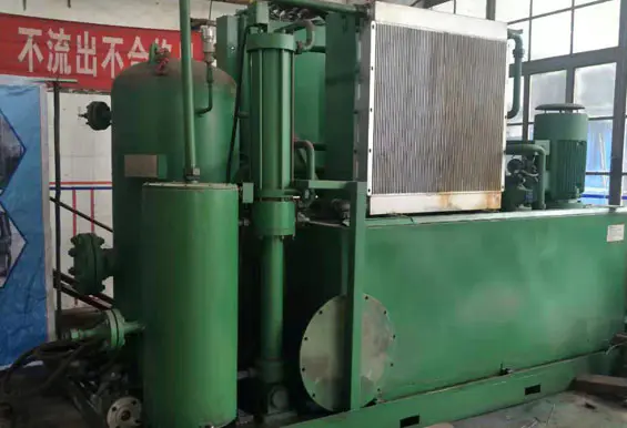
Final Product
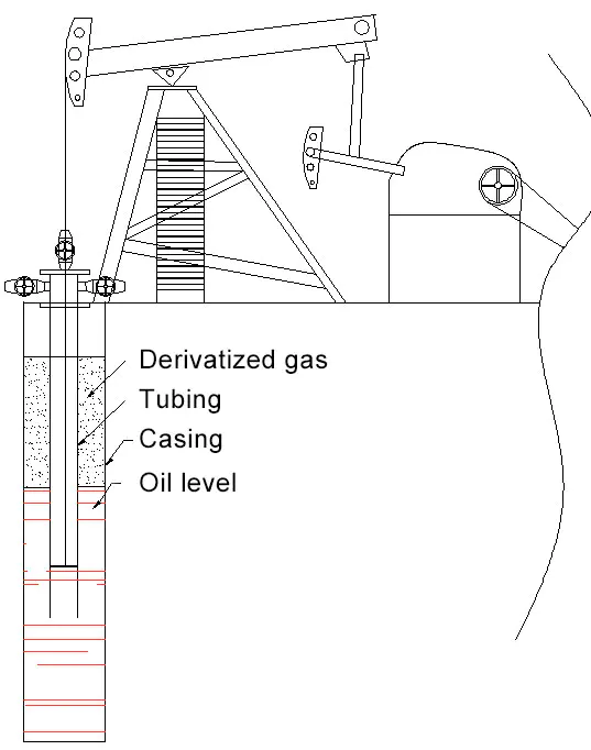
Customer’s Request and Working Condition
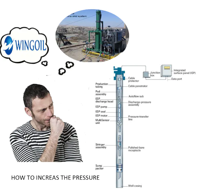
① In the oil and gas field, derivatized gas (natural gas) is generally produced in oil producing wells. When the gas volume of the derivatized gas is gradually increased, the gas pressure in the well will gradually increase, resulting in a decrease in the oil level and a decrease in pumping capacity. For the production of oil wells, the derivatized gas has a bad influence and is is necessary to carry out by pumping. The customer’s existing equipment can only be pressurized to 30 Bar, and he expects it to be pressurized to 70 bar.
② The production of derivatized gas is uncertain, and the equipment has intelligent work to adjust energy consumption according to its production.
③ The working environment of the equipment is used is in the desert area. The desert is seriously dehydrated, windy and sandy, the temperature difference between day and night is large, and the daytime temperature can reach 60 °C.
④ The equipment is highly served in different places.
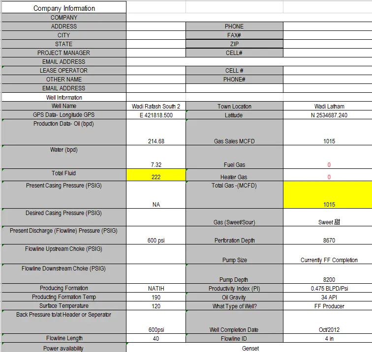
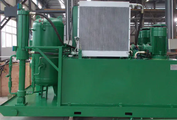
General View
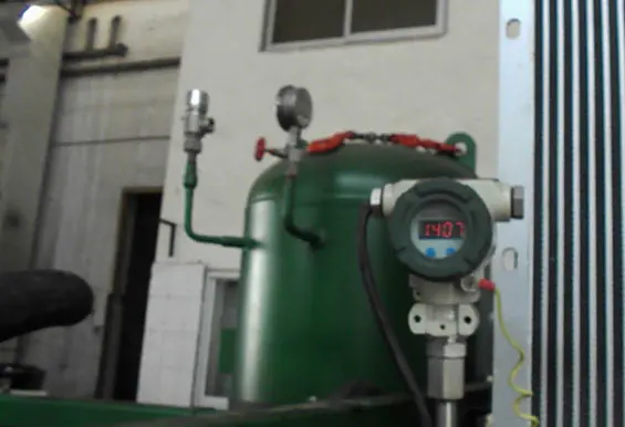
Field Parameters
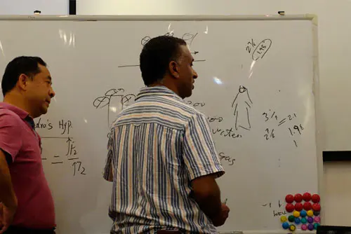
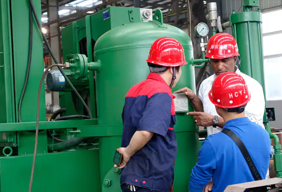
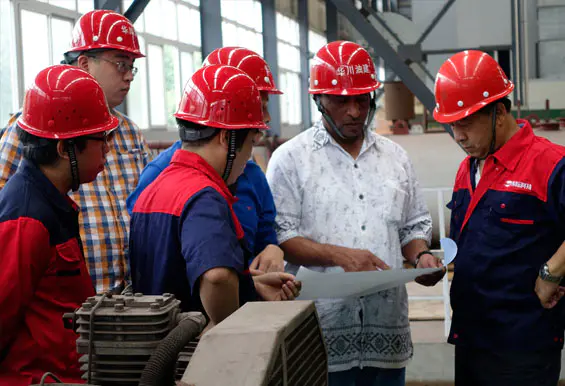
Technical Conference
Proposal Design
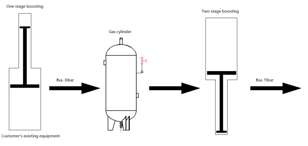
| Principle Design | The hydraulic booster pump is used to pressurize the derivative gas with an output pressure of 70 bar. |
| Start-stop Design | The pressure transmitter is used to detect the pressure of the wellhead derived gas, and the equipment is started when the pressure is sufficient. |
| Displacement Design | The pressure transmitter is used to detect the wellhead pressure. The higher the pressure, the higher the operating frequency. When the wellhead pressure is 0–200 psi, the operating frequency is 6 times/min. When the wellhead pressure is 0–600 psi, the operating frequency is 9 times/min. When the wellhead pressure is greater than 600 psi, the operating frequency is 12 times / minute |
| Power Source Design | Dynamitic power |
| Explosion Proof Design | The control components are all placed in the explosion-proof box. The explosion-proof grade of the test components (pressure transmitter, temperature transmitter, liquid level transmitter) is not lower than EXIIDT6, and the explosion-proof grade of the power components (explosion-proof motor) is not lower than EXIIDT6. |
| Temperature Control Design | Air cooling is used to circulate cooling for all parts of the equipment. Install high temperature resistant electrical components in the explosion-proof box. A partition is designed in the liquid storage tank to restrict the flow of the liquid and ensure sufficient heat exchange. |
| Operation Lifespan Design | The equipment is equipped with 3 explosion-proof motors. When running for a long time, the motor is automatically switched. |
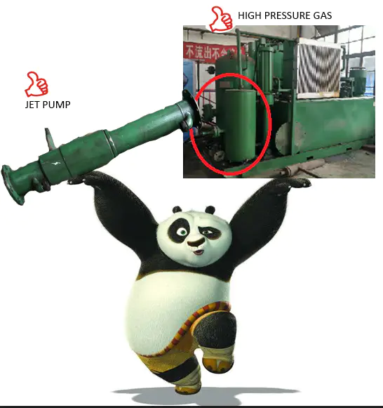
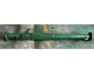
| Output Design | The equipment outlet is designed to be connected to a jet pump, so that the pressurized derivative gas can be injected into the main oil pipeline to improve the efficiency of the pipeline. |
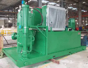
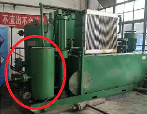
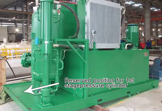
Structure Design
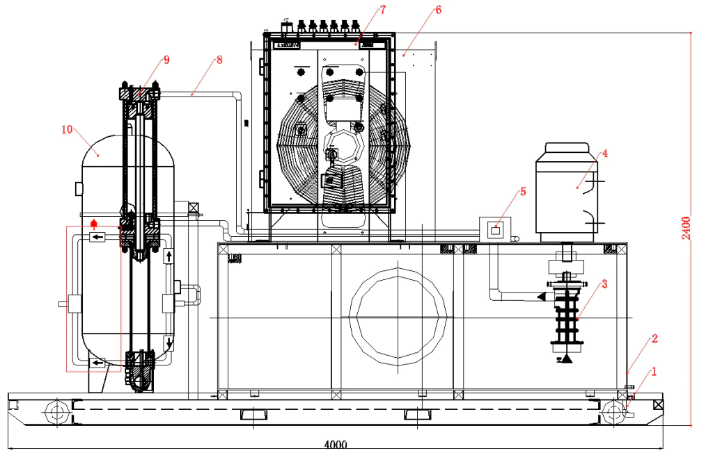
- 1: AR lifting lug
- 3: Hydraulic pump
- 5: Explosion-proof reversing valve
- 7: Explosion-proof distribution box
- 9: Pressurized cylinder
- 2: Fuel tank
- 4: Explosion-proof motor
- 6: Air-cooled radiator
- 8: Hydraulic oil pipe
- 10: Gas storage tank
| Skid structure | All parts are placed on the skid |
| Transportation design | AR lifting lug, for lifting and dragging |
| Maintenance design | There is a manhole on the fuel tank |
| Liquid leakproof design | The body is designed with a leak-proof device that allows liquid to drain out of the body. |
| Sandproof design | Make the necessary screen to prevent sand from entering the equipment components |
Specification
- Overall dimension:4000L×2100W×2600H
- Max. flow of 1st stagepressure cylinder:600L/min
- Stroke of 1st stagepressure cylinder:12次/min,9次/min,6次/min
- Displacement of 2nd stagepressure cylinder:9L
- Volume of Gas storage tank:300
- Max. pressure of hydraulic pump:5Mpa
- Max. flow of 2nd stagepressure cylinder:300L/min
- Stroke of 2nd stagepressure cylinder:16次/min
- Working pressure of Gas storage tank:4Mpa
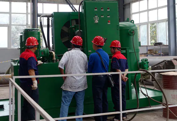
On-site Commissioning
The Come Out and Resolution of New Problems
There is a higher ambient temperature in the desert and compressed gas needs heat exchange for cooling down
Design Principle
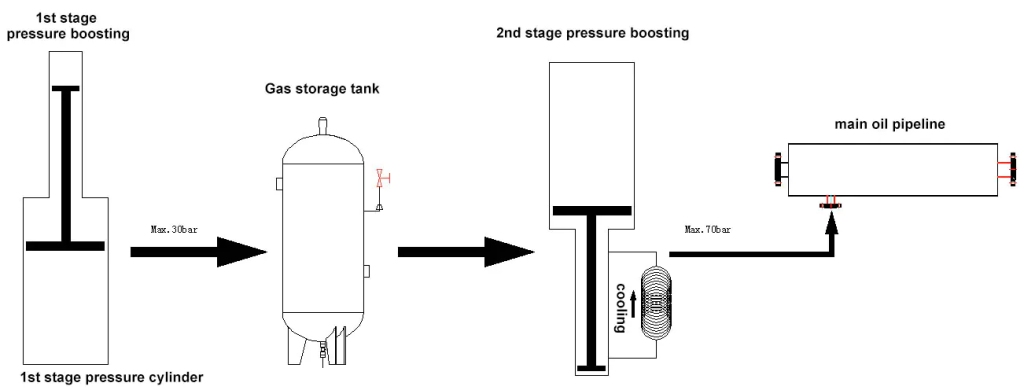
Cooling system: The compressed gas is cooled by the hydraulic oil of the equipment, in order to ensure that the temperature of the output gas is not higher than the ambient temperature.
Jet pump: The special spray gun designed with compressed high pressure gas can keep the principle of a high flow rate and improve the conveying efficiency.
Comparison of Proposal
| Existing Product | WINGOIL product |
| 30bar Max. output gas pressure | 70bar Max. output gas pressure |
| No temperature control device for output gas | With forced hydraulic oil cooling system, it can ensure the safety operation |
| No sand proof facility | With sand proof enclosur |
| Without buffer | With buffer and oil-gas separation unit |