About Relief Valves These 4 Things You Have To Know
In general, a relief valve is a type of valve that is designed to prevent overpressure conditions from causing an explosion, equipment failure, or the potential for injury or death to personnel. Relief valves can protect by venting fluid from a pressurized vessel or system or by adding fluid to prevent the formation of a vacuum condition, which could result in the collapse of a storage tank.
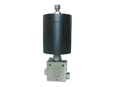
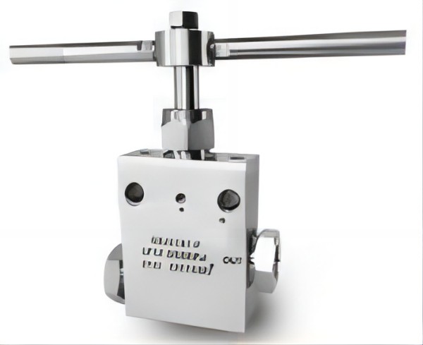
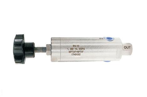
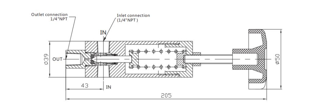
Components and operation of relief valves
The valve inlet nozzle is connected to the system or pressure vessel that is being protected.
A diaphragm or disc moves to control the flow of fluid through the valve and to the outlet port.
A spring that holds the disc in place and allows the valve to open when the system pressure exceeds a pre-determined value.
The relief valve will remain normally closed, preventing the system from ejecting fluid due to the action of the spring pressure holding the disc in place in the nozzle. If the system pressure increases to the point where the valve’s inlet pressure exceeds the set pressure, the inlet pressure will compress the spring, causing the disc to lift off the nozzle and allow fluid to exit through the outlet until the overpressure condition has been corrected and it returns to a value below the set pressure.
Materials of relief valves
Relief valves are produced using a range of materials, including polysulfone and brass. A steam release pressure valve, for instance, might be made of cast aluminum with a polyester diaphragm, but a bronze valve is a great option for low-temperature applications. Different media and pressure ratings call for different materials. Applications needing the preservation of hygienic or sanitary conditions can employ stainless steel. Many relief valves have parts made of materials other than the body’s substance. Relief valve seals and other comparable components use fluoro silicone, neoprene, propylene, and ethylene. The blending of different components results in a strong, long-lasting body that fully utilizes the sealing and elastic qualities of synthetic polymers and plastics. While not appropriate for every application, all-plastic valves can offer the advantage of being less prone to corrosion-related failure.
Relief valves can be made to work in air, steam, or liquid environments and to sustain extremely high internal pressures. Some valves have simple hand wheels or dials that can be used to program them to respond to various pressure levels. Others might be specifically created to respond to a certain pressure rating.
Specifications of relief valves
A list of some typical requirements for pressure relief valves is provided below. Finding an appropriate alternative to utilize will be made easier if you understand these parameters and how they relate to the application conditions. This summary serves as broad information only because different manufacturers may grade their goods differently.
The material from which the valve seal is made is referred to as the seal material.
Rated flow: the flow capacity of the valve when it is open.
Pressure range adjustment: the pressure range that can be set on the relief valve.
Operating temperature range: the temperature range for which the valve is rated.
The primary material of the valve body and mechanical components, excluding seats and seals.
Adjustment type: describes the type of adjustment provided, such as a screw, knob, or tamper-resistant.
The media type of a valve: describes the nature of the media for which it is rated, such as air, ammonia, refrigerant, fuel, oil, gas, water, steam, and so on.
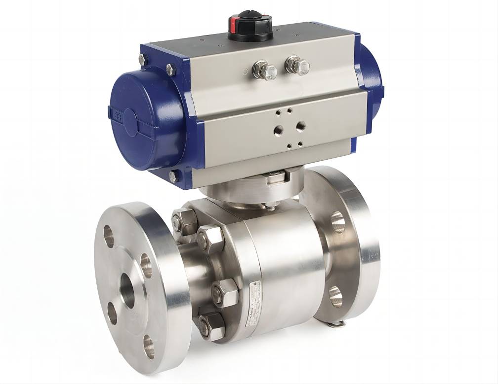
Mounting type: represents the mechanical method for mounting the valve to the system or pressure vessel, such as threaded, flanged, or manifold mount.

Selection considerations of relief valve for use require
Set pressure: the inlet static pressure value that causes the valve to open.
Back pressure: the value of the outlet static pressure which results from pressure in the discharge system, when direct venting to the atmosphere is not used.
Process media: the nature of the fluid contained in the pressurized system.
Connection size: the dimensions and types of connections at the valve’s inlet and outlet ports, including thread type when threaded.
Needed capacity: the flow rate or relieving capacity of the valve measured in volumetric units.
Accumulation: the incremental pressure increase over the system or unit under protection’s maximum allowable working pressure.
Valve manufacturers provide specific valve sizing procedures based on the media and condition pressures (see chapter 5 of reference 8 below for an example). These procedures include the equations needed to calculate heat energy input and required venting capacity under various application conditions. To validate any relief valve selections and installation procedures, qualified engineering resources should be consulted.