A Brief Introduction To Wellhead Pressure Control System
In the process of oil and gas exploration and development, how to balance the formation pressure drilling through the liquid column pressure in the well, and how to find, control, and deal with it in time when this balance is destroyed, and rebuild the pressure balance as soon as possible (referred to as balanced drilling and well control technology), not only related to the discovery, protection, and development of underground oil and gas resources but also directly related to the improvement of drilling speed, the prevention of blowout accidents, and the elimination of oil and gas pollution. It is a key technology with significant economic and social benefits.
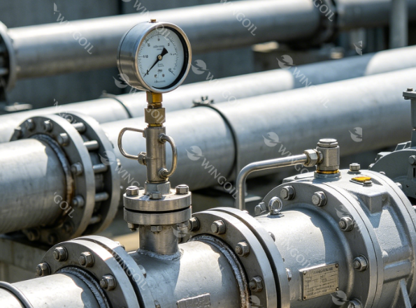
What is Wellhead Pressure?
Wellhead pressure – pressure at the top of the well, i.e., at its wellhead. It is measured by pressure gauges of the wellhead fittings. There are static and dynamic wellhead pressures.
In the abandoned well, static wellhead pressure is measured and is influenced by reservoir pressure, well depth, and filling medium density. It is equivalent to the difference between reservoir pressure and the hydrostatic pressure of the liquid column from the wellhead to the reservoir in terms of numbers.
The functioning well is used to monitor dynamic wellhead pressure, which is dependent on the same factors as static wellhead pressure Plus well rate or injection agent flow rate, pressure in the pipeline nearby the well, and pressure difference in shut-off components of the wellhead fittings. When a hydraulic fracture occurs in a gas well, the excess wellhead pressure (as compared to air pressure) can reach 100 MPa or higher.
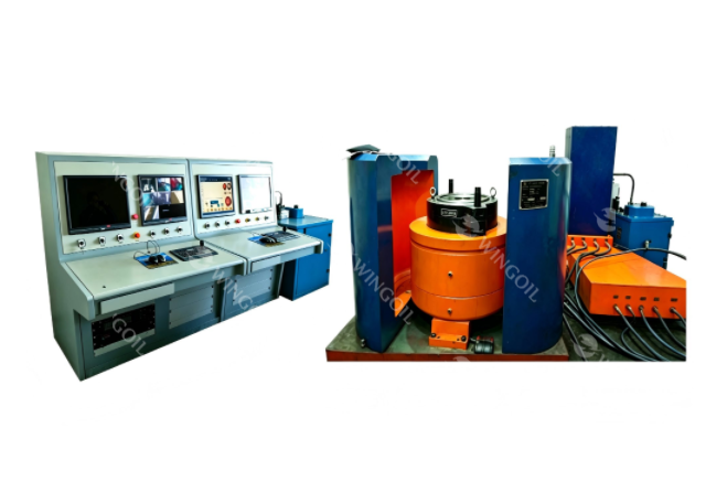
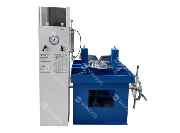
Components of Wellhead Pressure Control System
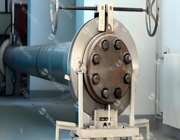
A wellhead pressure test is equipment installed at the surface of a complete oil or gas well that provides a structural and pressure-containing interface for the drilling and production equipment. In other words, this object is installed where casings are terminated by hanging the casings using casing hangers and seals. It consists of the following components:
- Casing head
- Casing spools
- Casing hangers
- Packoff seals, also called isolation seals
- Test plugs
- Mudline suspension system
- Tubing head
- Tubing hangers
- Tubing head adapter
This equipment is used for various purposes such as:
- Hanging or suspending casing by means of casing hangers and seals.
- It provides a pressure seal as well as strength to hold the hanging weight of casings.
- Provides a means of tubing suspension.
- BOP is attached to the wellhead during drilling operations.
- X-mas tree also called a Christmas tree is attached to the wellhead during the production of hydrocarbon streams.
- All the well access for any workover operations is through the wellhead.
The nominal diameter of wellheads is typically 2, 3, 5, 10, and 15 inches, with operating pressure ratings ranging from 2000 to 15000 psi.
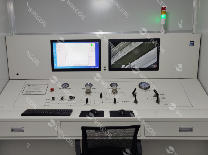
How does Wellhead Pressure Control System Work?
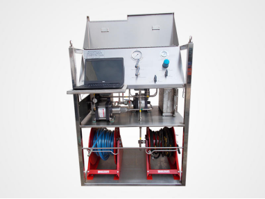
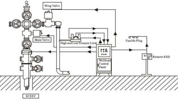
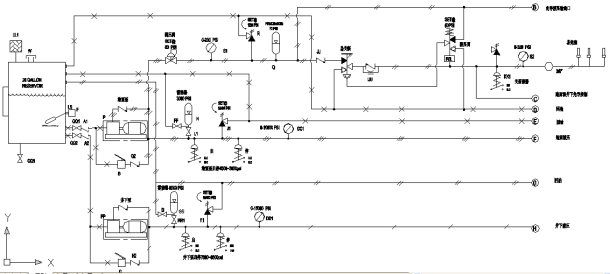
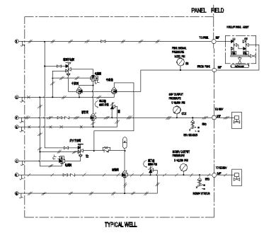
Under the action of an electric booster pump or a manual booster pump, the hydraulic oil is boosted, and the size and start and stop of the booster pump are controlled by a pressure switch. The pilot pressure controls the action of the hydraulic control valve, and the system hydraulic control valve controls the conduction or closure of the high-pressure hydraulic oil, thereby controlling the pipeline system, that is, opening the surface and underground safety valves.The pressure of the high-pressure relief valve and the low-pressure relief valve control system is guaranteed to work within a certain range. After the explosion-proof solenoid valve or panel switch valve receives the closing signal, the pilot pressure of the high-pressure hydraulic three-way valve and the low-pressure hydraulic three-way valve is released, and then the valve is released. The pressure valve is automatically reset, instantly reducing the system pressure to 0, that is, closing the ground and underground safety valves. The main working principle is as follows:
Wellhead Pressure Formula
The following formula is used to calculate the Wellhead Pressure.
Pwh = Pbh / e^((Sg/R*H)/Tav)
Variables:
- Pwh is the Wellhead Pressure (psia)
- Pbh is the bottom hole pressure (psia)
- H is the true vertical well depth (ft)
- Sg is the specific gravity of the gas
- R is the universal gas constant (53.63 ft-lb/lb-r)
- Tav is the average temperature (Rankin)
How to Calculate Wellhead Pressure?
The following steps outline how to calculate the Wellhead Pressure.
- First, determine the bottom hole pressure (psia).
- Next, determine the true vertical well depth (ft).
- Next, determine the specific gravity of gas.
- Next, gather the formula from above = Pwh = Pbh / e^((Sg/R*H)/Tav).
- Finally, calculate the Wellhead Pressure.
- After inserting the variables and calculating the result, check your answer with the calculator.