Applications and common types of quick couplings
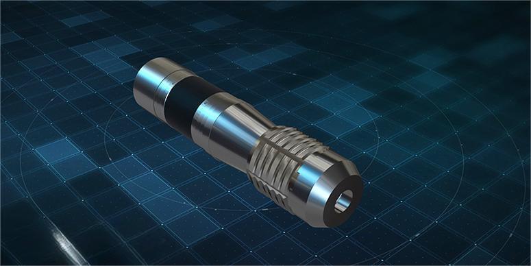
Quick couplings are devices installed at the outer end of the work equipment of various types of construction and earth-moving machines. They make it easier to quickly swap out working tools or buckets.
What is the quick coupling
In order to transfer power or torque from one shaft to another shaft, couplings are mechanical devices. Only if the shafts are parallel can power be transferred using various gear combinations or drives.
Fluid lines are connected to equipment using a particular form of connector called a quick coupling. In hydraulic or pneumatic systems, quick-connect couplings are employed, particularly in time-sensitive situations where a quick method of connecting lines without losing fluid pressure is required.
General application of quick couplings
To transmit power from the driving shaft to the driven shaft.
To connect or couple 2 components which are manufactured separately eg. output motor shaft and generator.
To introduce extra flexibility while transmitting power in case of space restrictions.
To introduce protection against overloads.
To reduce the transmission of shock loads from one shaft to another by using flexible couplings.
Types of quick couplings
This article discusses the six most common locking mechanisms used in fluid power applications among the various quick coupling methods.
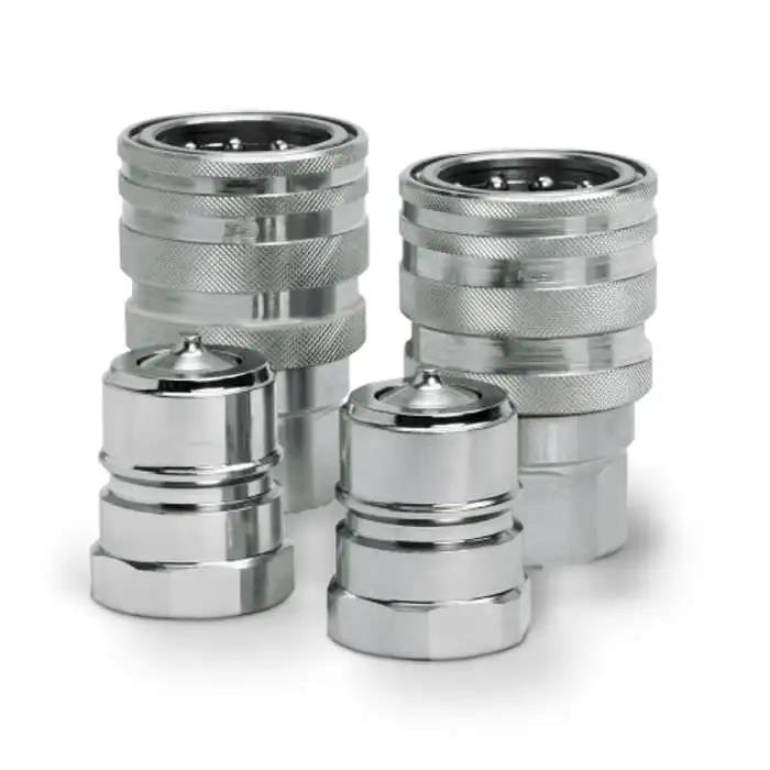
- Ball lock coupling
The ball lock coupling has the most applications and is the most popular design. In holes around the ID of the socket body, there are a number of balls. In order to prevent the ball from falling into the space left by the plug when the coupling is severed, these holes are typically tapered or stepped to minimize their diameter near the inner diameter of the socket body.
The ball is pushed in the direction of the ID of the socket body by a spring sleeve that surrounds the socket body’s outer diameter. To allow the ball to move freely after plugging it in, press the sleeve backward. Once the plug is in position, releasing the sleeve will cause the ball to move toward the locking groove on the plug’s outer diameter. Push the sleeve back to make room for the ball to slide outward and remove the plug in order to detach.
- Roller lock couplings
In order to attach end to end in the groove or groove around the socket ID, roller lock couplings employ lock rollers or pins. The ramp on the plug’s outer diameter forces the rollers outward as it is inserted. The roller will slip into the fastening groove on the plug’s outer diameter once it has been inserted the required amount. Release the stopper by retracting the locking sleeve, which will cause the roller to move outward along the ramp on the stopper’s outer diameter.
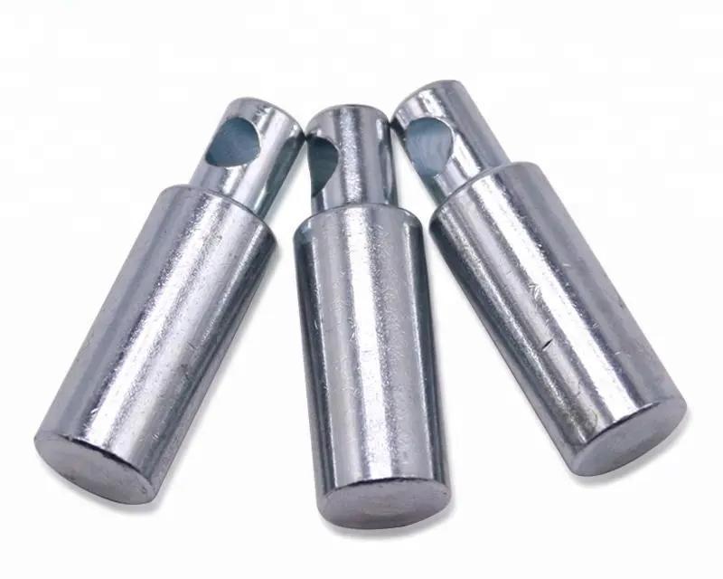
- Pin-lock joint
Because there is no need to retract the outer sleeve for connection, the pin-locked joint simply requires one hand to force the connection. The pins in this design are placed in a truncated cone shape around the ID of the socket body. Pushing the plug into the socket causes the pins to slide back and out because of the slope of the plug. To secure the plug in the socket, remove the pin. Pull back the spring sleeve to pull the locking pin out of the groove and free the plug from the socket.
- Flat connector
Flat joints almost eliminate spillage by limiting leaking to one drop or less when separated. Additionally, it is simple to keep the flat mating surface clean to avoid contaminating the hydraulic fluid during reconnection. Each mating side of the flat non-leakage joint (Figure 4) features a poppet shut-off valve. Most only allow for the development of an oil film on the coupling mating surface during disengagement and keep air out during connection. Additionally, they are made to limit flow as little as possible, reducing pressure loss while the device is in use.
- Bayonet couplings
Bayonet couplings, particularly plastic couplings for light pneumatic equipment, are frequently employed in a variety of applications and rely on well-known twist-lock systems. When the plug is inserted into the socket, the lugs on its outer diameter engage with the grooves in the socket sleeve to provide a connection between the two connecting parts. To secure the lugs, swiftly turn. To separate the two pieces, turn the plug counterclockwise.
- The lock ring coupling
The split ring used by the lock ring coupling is situated in the socket’s groove and groove. When the plug is pushed into position, the ring at the opening is separated by the plug’s bevel until the ring clamps onto the plug behind the fixed shoulder. The ring expands when the outer sleeve is rotated, freeing it from the fixed shoulder and allowing the two parts to be pulled apart. With this design, a compact space can accommodate the highest flow rate for typical workshop air applications. Instead of split rings, jaws are used in this design’s variant to lock the components together.
Summary
Quick connect coupling uses and varieties are covered in this article. Quick couplings are frequently used in high-pressure quick-change applications such as hydraulic wrenches, bolt tensioners, torque tools, and high-pressure pumps.