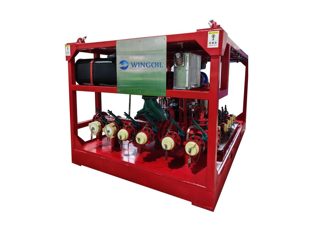

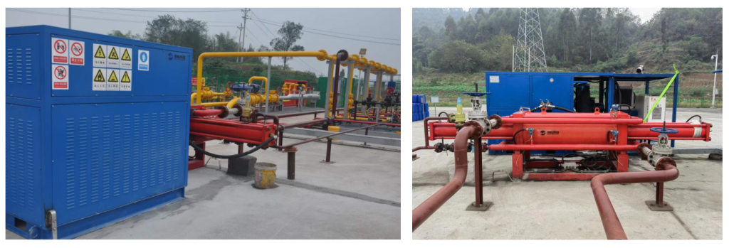
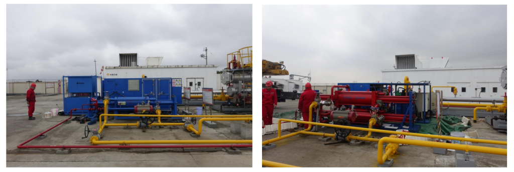
Hydraulic Multiphase Transfer Pump System
- It is an innovative and cost-efficient booster pump compression system designed by Wingoil, consisting of one automated intelligent hydraulic system, multiphase pumps, and power sources (electric power or natural gas generator), and/or gas lift unit. It can achieve the functions of mixed exploitation and transfer of gas, fluids and solids from wells, and is suitable for gas wells and oil-gas mixed wells.
Share to
Overview
It directly pumps oil, water, natural gas, and solids from wellhead into the pump system in between without three-phase separators. Through pumping, the pressure of the wellhead can be significantly reduced, which enlarges the pressure differential between the bottom hole and wellhead, thus improves the flow rate, gas production and liquid carrying capacity, achieving the goals of production stabilization and rising.
With continuous lowering of the liquid column height, the discharge of formation water accelerates, which extends the production period of the wells and enhances the exploiting rate of gas wells to a certain extent.
Application
The hydraulic multiphase transfer pump is mainly used in the middle and late production stages of gas well exploitation. After the high-yield flowing phase ends, the gas well output drops significantly compared to the initial stage, and the decline accelerates due to the back pressure from pipelines. There are multiple reasons for this, primarily the decreased gas storage in formation—especially, the reduced fluid flow rate in the near-wellbore area and increased liquid volume, which lead to lower gas well output and weakened water-carrying capacity of gas. This results in increased liquid accumulation in the wellbore and a higher liquid column, further impacting gas well production.
Feature
1. Reduces the wellhead pressure of gas wells or well clusters, increases output, and extends the production cycle of gas wells.
2. Enables mixed pumping and transportation of gas, liquid, and small amounts of solids without the need for three-phase separation. The inlet of the multiphase pump can be directly connected to the flowline, avoiding a pressure drop of approximately 0.2Mpa caused by three-phase separation.
3. Compared with lower efficiency of other kinds of pumps, its power consumption is about 50% lower based on the same gas production capacity and pressure differential.
4. Suitable for gas wells with wellhead of low pressure, as it can reduce the wellhead pressure to 0.1Mpa, as well as gas well clusters with high pressure wellhead and high output.
5. The hydraulic station system is controlled by PLC automation. It is intelligent and explosion-proof.
6. All sealed rings with long service lives.
7. Integrates multiphase pump system and gas lift functions in one device, facilitating operations.
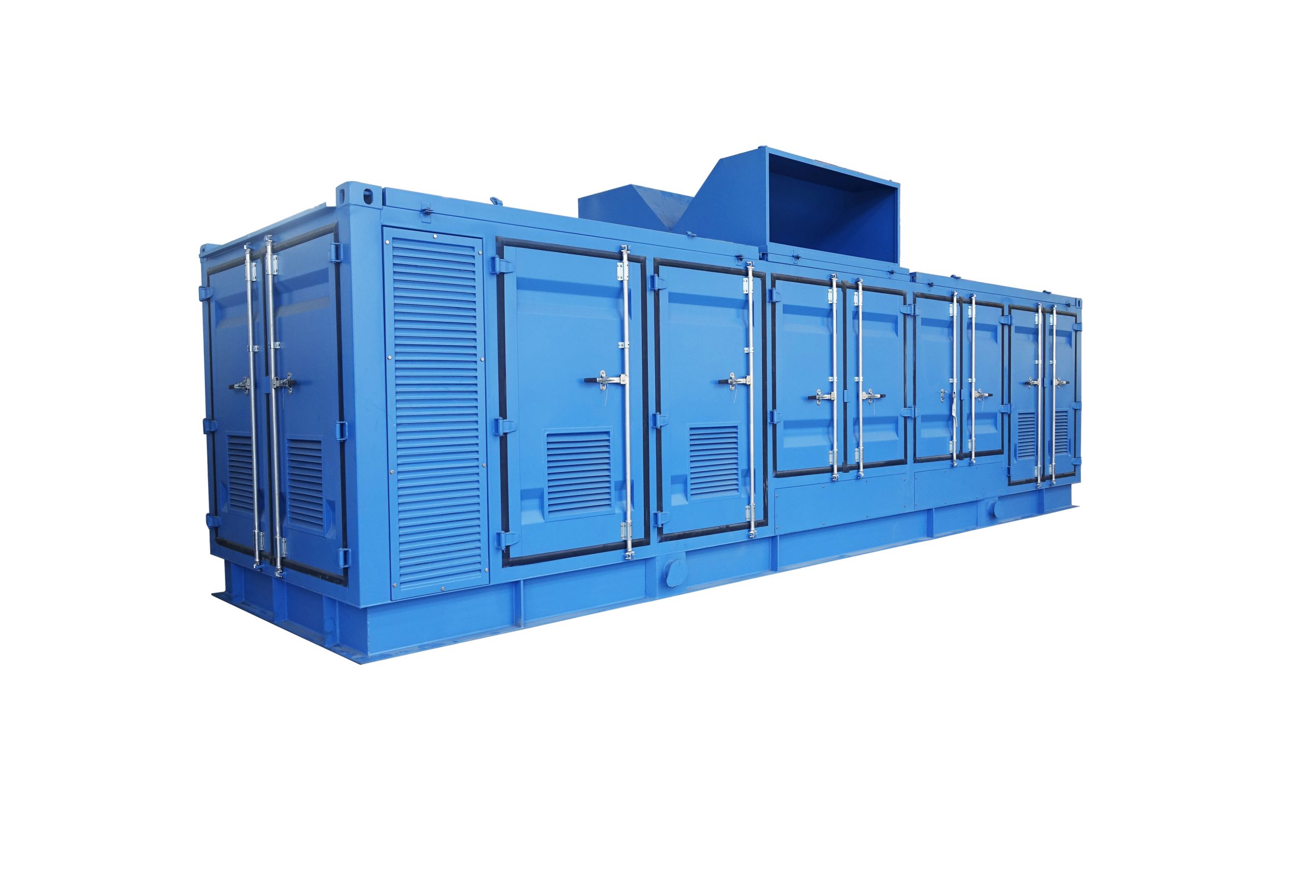
8. Skid-mounted structure for easy transportation and installation.
9. Uses self-produced natural gas from gas wells (clusters) as the gas lift medium, lowering gas extraction costs and significantly reduced power consumption. Suitable for single-well gas lift and well cluster circulation gas lift processes.
10. Equipped with remote control and monitoring system.
11. Short maintenance time and all maintenance can be done on-site.
12. Devices can be configured in series or parallel: multiple devices in series can increase output pressure; multiple devices in parallel can increase discharge flow.
13. Provides complete quality marks, reports, explosion-proof certificates, as well as various related equipment manuals, on-site work scheme, emergency response plans, and other relevant documents.
Multiphase Transfer Pump System
| Model | Displacement (10K sq.m/d @ Suction Pressure 1.0Mpa) | Suction Pressure(Mpa) | Discharge Pressure (Mpa) | Max. Pressure differential(Mpa) | Motor Power (KW) | Equipment Size(M) |
| WY-H-1.8X5.5 | 5.5 | 0.1-3 | 1.9-4.8 | 1.8 | 90 | 6*2.5*2.5 |
| WY-HⅡ-2.6X10 | 5.5 | 0.1-3 | 3.7-6.3 | 3.6 | 90+55 | 9*2.5*2.5 |
| WY-HⅡ-1.8X11 | 11 | 0.1-3 | 1.9-4.8 | 1.8 | 90+90 | 9*2.5*2.6 |
| WY-HⅡ-2.6X10 | 10 | 0.1-3 | 2.7-5.6 | 2.6 | 160+75 | 9*2.5*2.6 |
Multiphase Transfer Pump and Gas Lift Integrated System
| Model | Displacement (10K sq.m/d @ Suction Pressure 1.0Mpa) | Suction Pressure(Mpa) | Discharge Pressure (Mpa) | Gas Lifted Pressure(Mpa) | Motor Power (KW) |
| WY-HⅡ-1.8X5.5/15 | 5.5 | 0.1-3 | 1.9-4.8 | 15 | 90 90 |
| WY-HⅢ-1.8X11/15 | 11 | 0.1-3 | 1.9-4.8 | 15 | 90+90 90 |
| WY-HⅢ-2.6X10/15 | 10 | 0.1-3 | 2.7-5.6 | 15 | 160+75 90 |
| WY-HⅢ-1.8X5.5/25 | 5.5 | 0.1-3 | 1.9-4.8 | 25 | 90 90+90 |
| WY-HⅣ-1.8X11/25 | 11 | 0.1-3 | 1.9-4.8 | 25 | 90+90 90+90 |
| WY-HⅣ-2.6X10/25 | 10 | 0.1-3 | 2.9-5.6 | 25 | 160+75 90+90 |
Gas Lift Unit
| Model | Displacement (10K sq.m/d @ Suction Pressure 1.0Mpa) | Suction Pressure(Mpa) | Discharge Pressure (Mpa) | Motor Power (KW) | Equipment Size(M) |
| WY-Q15X1.5 | 1.5 | 2-5 | 15 | 90 | 6*2.5*2.5 |
| WY-Q25X3.0 | 3 | 1-5 | 25 | 90+90 | 9*2.5*2.6 |
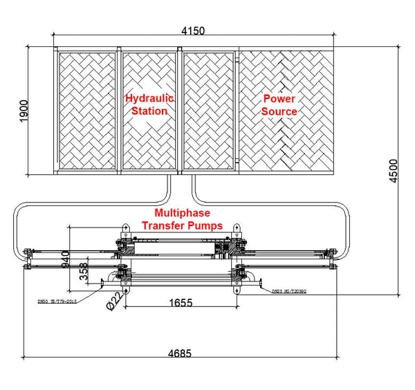
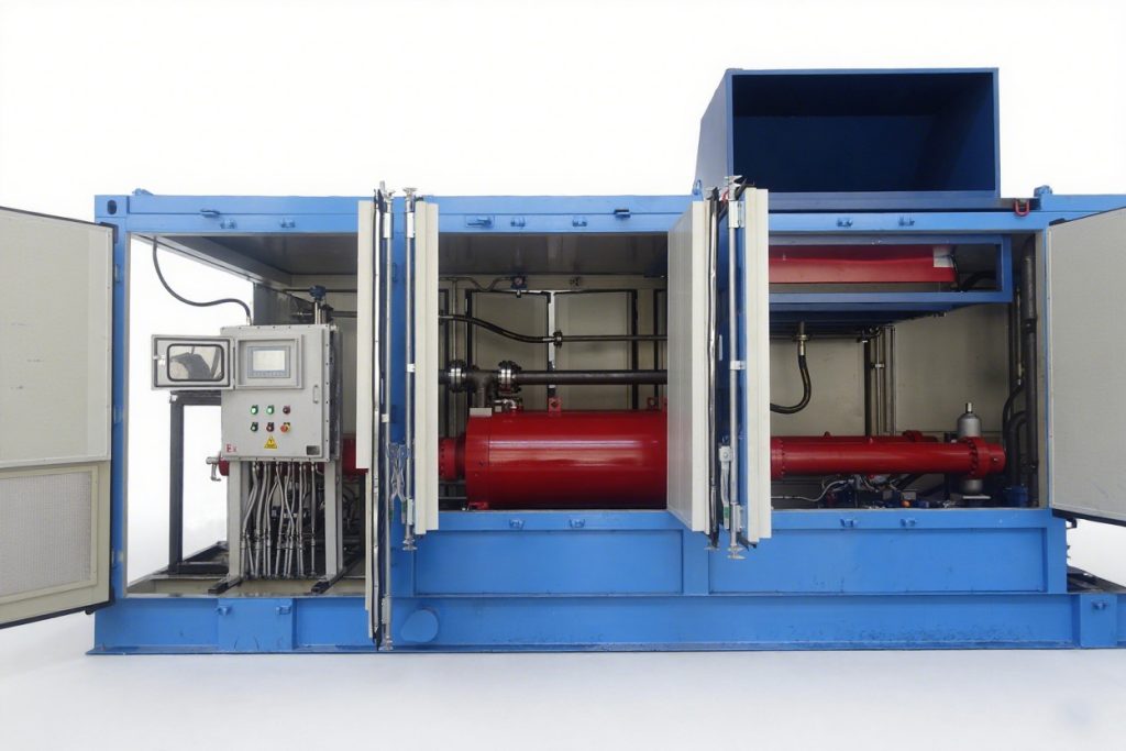
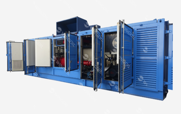
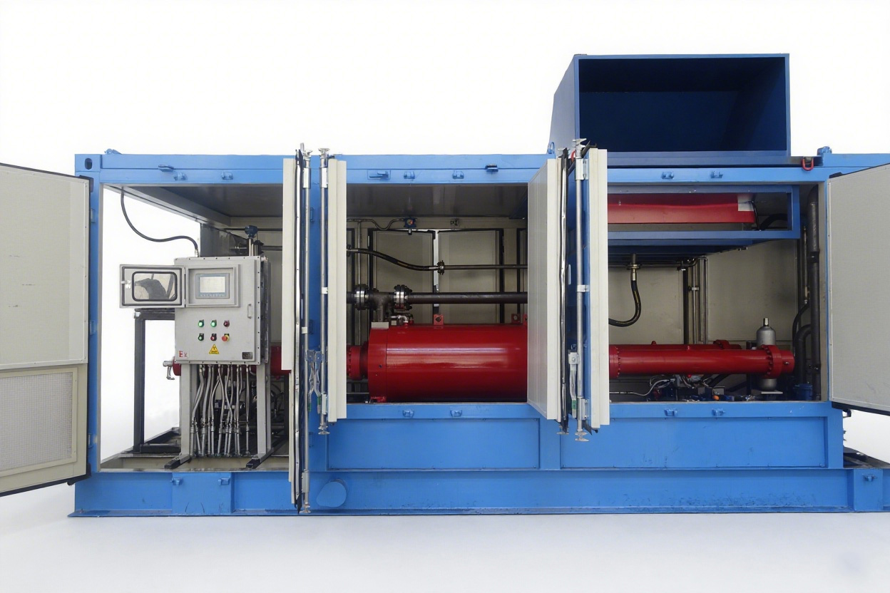
Hydraulic Multiphase Transfer Pump System mainly consists of three or four parts:
1. Automated intelligent hydraulic system
2. Multiphase mixed transfer pumps
3. Power source (electric power or natural gas generator)
4. And/or gas Lift Unit
————————————————————————————————————————————————————————————————————————————————————————————————————————————————————