The Best Guide to Needle Valves
Needle valves are specialized valves that are used to measure fluid flow. Their primary application is in small systems such as instrumentation or fuel regulation, where the ability to precisely and repeatedly control the flow of fluid is highly desirable. There are two main body configurations for needle valves.
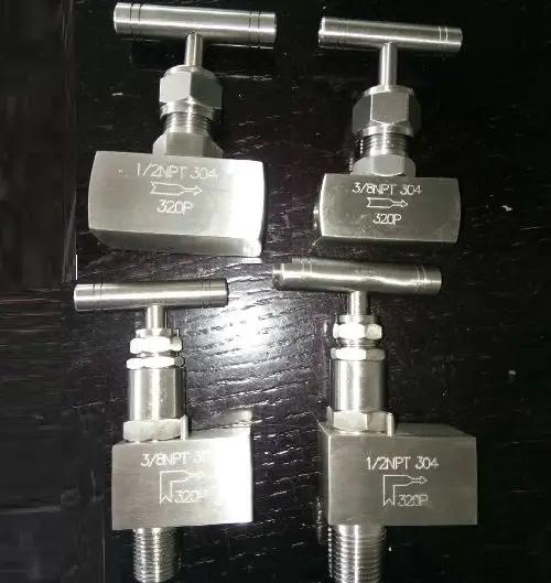
The layout of needle valves
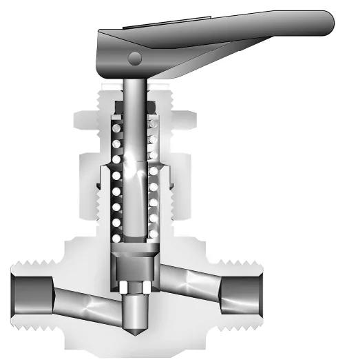
The valve body and seat, the stem and stem tip, and the packing and bonnet are the three major components of a needle valve assembly. Needle valves are often small enough that their bodies can be machined directly from hex or square bar stock. Typical configurations include Z- and L-shaped flow paths through the body, which are also known as globe and angle patterns.
(1) Body and Seat of needle valves
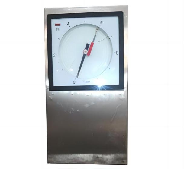
Fine threads are typically incorporated into the stem to allow for micrometer-like adjustment of the needle relative to the seat. To prevent vibration from changing valve settings, a locking means is frequently provided, either internally or via a set screw, locknut, etc. on the stem. A scale is sometimes included to allow for accurate flow rate resetting. Manufacturers will frequently publish curves illustrating the mostly linear relationship between stem turns and the flow coefficient, Cv.
(2) Stem and Stem Tip of needle valves
Depending on the intended application, the stem tip can be relatively long and tapered or somewhat short and blunt. The seat is usually tapered to match the taper of the needle. Tapered stem tips are used to regulate service. In small orifice valves, vee-point stem tips allow for leak-free shutoff. To provide full flow with a few stems turns, blunt vee-point stem tips are used. A choice of stem tip material is frequently available, with metal for long life or replaceable PCTFE for lower sealing torque. Non-rotating stem tips are used to keep the stem tip and seat from galling.
(3) Packing and Bonnet of needle valves
The packing in the bonnet ensures that the stem rotates freely. Packings are frequently made of O-rings, PTFE, or graphite. A packing or gland nut is used to adjust packing pressure. Two-piece stems are sometimes used to isolate the stem threads from the media and keep thread lubricant from leaking into the process fluids. The bonnet is sometimes formed as an integral part of the valve body, while other times it is a separate part threaded into the body or held in place with a nut. When the valve is fully opened in environments where fugitive emissions are a concern, a back seat is provided against which the stem seals. Most designs include a method to prevent the stem from being completely backed out of the valve.
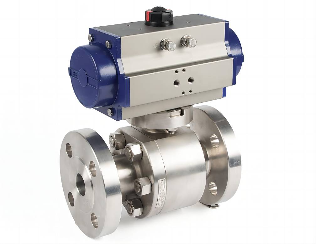
Needle valves are typically operated by hand, but there are automatic versions available. Needle valves provide positive shut-off and can be used as shut-off valves, but other, more cost-effective valves are available if this is the only requirement and not metering. When closing a needle valve, exercise caution because excessive torque can damage the stem tip or the seat.
Certain designs are available that allow for faster flow adjustment with fewer stem turns than standard designs.
Applications of needle valves
Needle valves are used in power plants, refineries, and chemical plants, as well as in oil and gas exploration, laboratory analysis, and other applications. They are used in gas chromatography, sampling, instrument air, and other applications that require precise flow metering.
Needle valves are commonly used to reduce the flow rate of liquids or gases so that they can be introduced to measuring instruments that would otherwise be damaged by the full flow. Another application is controlling piston speed by regulating the flow to air cylinders. They are frequently used to regulate fuel flow in automated combustion control systems. Governor-controlled pumps frequently employ needle valves to protect the governor from damaging surges. Needle valves are sometimes used as components of larger control valves.
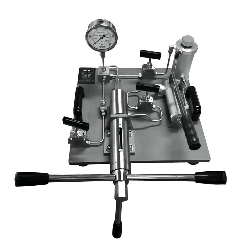
Stainless steel, carbon steel, nickel-copper alloys, and brass are common materials used for valve bodies. Specifiers must consider system pressure, operating temperature, required flow rate, and construction materials when selecting needle valves. There are special designs for dealing with high pressures, high temperatures, corrosive fluids, and so on. To accommodate higher flow rates, some valves can be ordered with different orifice diameters. Needle valves are frequently mounted in control panels, and manufacturers will typically include components with their valves to allow for these arrangements.
Port connections are commonly available in NPT thread, compression fitting, or socket weld configurations. Manufacturers can provide valves that are certified for oxygen service or helium leak testing in certain critical operations, for example.
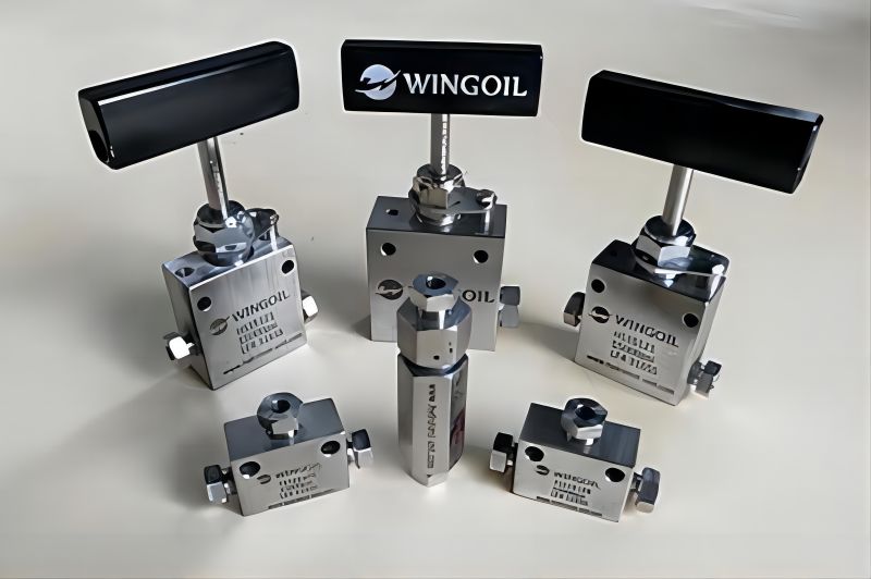
Valve handles are offered in a variety of styles and materials, including aluminum crosses and ABS wheels, as well as in an array of colors to provide both tactile and visual cues to guide valve operation.
Considerations when using needle valves
The flow factor Cv for each valve is published by the manufacturer, and it expresses the flow rate of a valve in gallons per minute of water at 60°F with a pressure drop of 1 psi across the valve. This factor can then be used to calculate the expected flow rates through a specific valve design for other media, temperatures, and pressures. A flow coefficient similar to this one is used to calculate the flow rate of gases through a valve.
Instrument valve manufacturers will typically categorize their needle valve offerings based on pressure, temperature range, and flow factor (which often ranges due to port connection options). They also know which applications their valves are best suited for and can advise needle valve specifiers on these matters.
Summary
This article provided a brief overview of needle valves, including valve design, applications, and considerations for selection.