Ultimate Guide to BOP Hydrostatic Pressure Testing: Standards, Procedures, and Equipment Selection
In the field of well control safety, the Blowout Preventer (BOP) serves as the final barrier to ensure drilling operation safety. Operating under extreme high pressures and severe formation fluid shocks at the wellhead, any minor seal failure or structural defect in the BOP system can lead to a catastrophic blowout.
BOP Hydrostatic Pressure Testing is the standard method for verifying the sealing performance and structural integrity of the BOP stack, choke and kill manifolds, and high-pressure control valves.
In this post, we will provide an in-depth analysis of BOP hydrostatic pressure testing requirements, standard operating procedures, common troubleshooting, and a selection guide for high-efficiency, safe high-pressure testing equipment.
What is BOP Hydrostatic Pressure Testing?
Blowout Preventer Hydrostatic Pressure Testing is a professional technical inspection procedure that applies a predetermined high pressure to drilling BOPs and associated well control manifolds in a controlled environment using an incompressible liquid medium (typically water or an aqueous solution with a rust inhibitor) to inspect their structural integrity and sealing performance.
As an indispensable safety and compliance element in oil and gas drilling engineering, the core components of BOP hydrostatic pressure testing include:
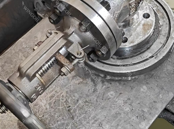
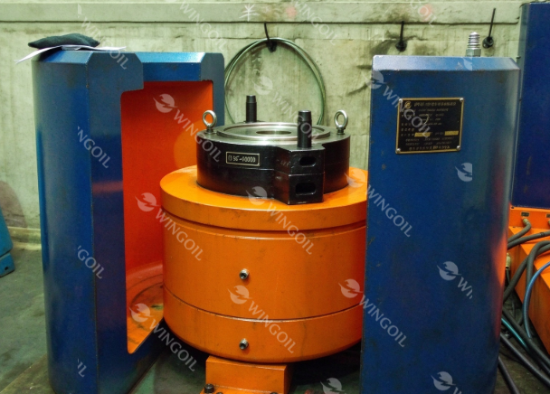
Test Objects: Annular BOPs, Ram BOPs (including pipe rams, blind rams, and shear rams), drilling spools, choke and kill manifolds, and high-pressure valves.
Working Principle: The test medium is forced into the BOP cavity using a high-pressure test pump, which increases the pressure from a lower pressure value (e.g., 200-300 psi) to the RWP of the equipment (5,000 psi, 10,000 psi, 15,000 psi, and above), maintaining it at the hold time and measuring the pressure curve with pressure sensors and recorders to check whether there is any leakage or deformation of the equipment.
Core Purpose: To guarantee that the BOP would be able to close off the well in case of an unexpected increase in pressure within the well.
Why is BOP Hydrostatic Pressure Testing Critical for Oil and Gas Drilling Operations?
The BOP system serves as the essential “last line of defense” in oil and gas drilling operations and is thus subject to exposure to extreme pressures, fluids that can cause corrosion, and tough wellbore environments. In addition to being a means to meet compliance requirements like API 53, the standardized process of testing of BOP systems’ hydrostatic pressure is an integral part of ensuring safety in the oilfield operation.
1. Eliminating Pressure Boundary Failure Risks
During drilling operations, the BOP stack, choke and kill manifolds, and high-pressure valves are constantly subjected to sudden high-pressure formation fluid shocks. Through rigorous hydrostatic testing, the structural integrity of the equipment at its Rated Working Pressure (RWP) can be precisely verified, eliminating the risk of catastrophic rupture of shells, flanges, or high-pressure lines at the source.
2. Detecting Critical Sealing and Leakage Issues
Whatever be the reason for the leaks—high-pressure seal aging, wrong fit during assembling, scratched sealing surfaces, or wear of components—any of these is capable of causing a fatal leakage from the wellhead. Using the concept of incompressibility of liquids, hydrostatic tests can reveal even micro-leaks with extremely high sensitivity to ensure “zero-leakage” tightness in annular and ram BOPs.
3. API Compliance & Quality Assurance
Standard pressure testing procedures are an integral part of the QMS for oilfield service companies, drilling contractors, and equipment manufacturers. Comprehensive test reports and certification of compliance not only fulfill the mandatory standards laid down by API 53 and API 16A but also ensure the generation of critical documentation credentials for equipment installation, 14 day cycle testing, and safety inspections.
4. Enhanced Data Transparency & Automation
In today’s advanced oilfield service industry, the use of pressure gauges with manual visual inspection does not satisfy the audit and safety criteria required.
Digital Traceability: The application of high accuracy pressure transducers, Electronic Data Acquisition System (DAS), and real time pressure-time trace recording devices produces fool proof test report.
Automation Efficiency: The adoption of an automated BOP testing system results in standardized testing process with minimum errors and maximum efficiency and safety.
Core Industry Standards for BOP Hydrostatic Testing (API Standards)
To ensure standardization and safety in field operations, the global oil and gas industry generally follows technical specifications established by the American Petroleum Institute (API) and related regulatory bodies (such as BSEE).
API Standard 53
Specification Name: Blowout Prevention Equipment Systems for Drilling Wells.
Core Requirements: Details the pressure testing standards, hold times, and acceptance criteria for well control equipment after initial installation, routine testing (14-day cycle), and workovers.
API Spec 16A
Specification Name: Specification for Drill Through Equipment.
Core Requirements: Specifies the Factory Acceptance Test (FAT) standards for BOPs upon manufacture and remanufacture, including testing limits for Rated Working Pressure (RWP).
Low-Pressure vs. High-Pressure Test
According to API 53, a complete BOP hydrostatic pressure test must include both low-pressure and high-pressure phases, which cannot replace each other:
| Test Item | Low-Pressure Test | High-Pressure Test |
| Test Pressure | 200 – 300 psi (1.4 – 2.1 MPa) | Rated Working Pressure (RWP) (e.g., 5,000 / 10,000 / 15,000 psi) |
| Hold Time | At least 5 minutes (Surface equipment) | At least 5 minutes (Surface equipment) / Some deepwater specs require 10 minutes |
| Detection Focus | Soft seals, lip seals, valve leakage under low pressure | Metal seals, housing pressure capacity, high-pressure sealing of rams and packer elements |
| Why Low-Pressure First? | Many self-sealing rings are forced tight under high pressure, masking micro-leaks; initial seal failures are only exposed at low pressure. | Verifies overall structural strength and high-pressure sealing limits under extreme conditions. |
How to Do BOP Hydrostatic Testing (Step-by-Step Procedure)
Standardized operating procedures ensure accurate and valid test data while maximizing field safety. Testing must strictly follow API Spec 16A and API STD 53 standards. The following process describes common testing stages:
Step 1: Preparation & Isolation
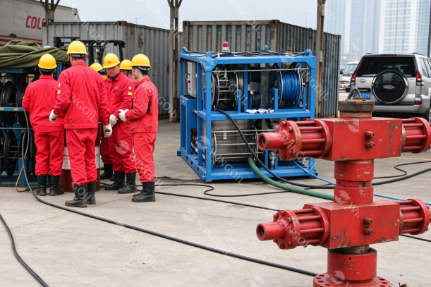
Before testing, flush the BOP cavity with clean water to remove mud and debris to protect the packer element and ram sealing surfaces; run a test plug or testing cup to isolate the wellbore and prevent high pressure from damaging the formation or completion string. Concurrently, check the test pump station, pressure gauges, and recorders (ensuring they are within the calibration validity period), and establish a safety cordon.
Step 2: Filling & Bleeding Air
Fill the BOP cavity with clean water or water-based medium and open the highest bleed valve. All air from within should be removed because otherwise, there will be pressure changes due to the air compressing or due to the dangers of water hammer while depressurizing. When the vent line starts flowing with clear water, then close and lock the bleed valve.
Step 3: Low-Pressure Phase
Pump station should be started and pressure should be gradually raised up to 200-300 psi, followed by stopping of pumping and holding of pressure for at least 5 minutes. At this stage, there is an attempt to prove the tightness of the system in terms of stability of pressure without its continuous decline.
Step 4: High-Pressure Phase
Increase the pressure in stages to the BOP Rated Working Pressure (RWP, such as 10,000 psi), maintaining the pressure for at least 5 minutes (as required per standards). Conduct independent high pressure testing on all components in order: annular BOP (to pressure as per API 53); pipe rams (to pressure of drill pipe); blind/shear rams (to open hole); and choke/kill manifolds (valve by valve).
Step 5: Depressurization & Logging
After testing, slowly bleed off pressure via the fine-adjustment pressure relief valve. Sudden explosive depressurization is strictly prohibited to prevent impact damage to valve seats and packer elements. After complete depressurization, export the digital “pressure-time” curve, which is then signed and verified by a qualified engineer for archiving.
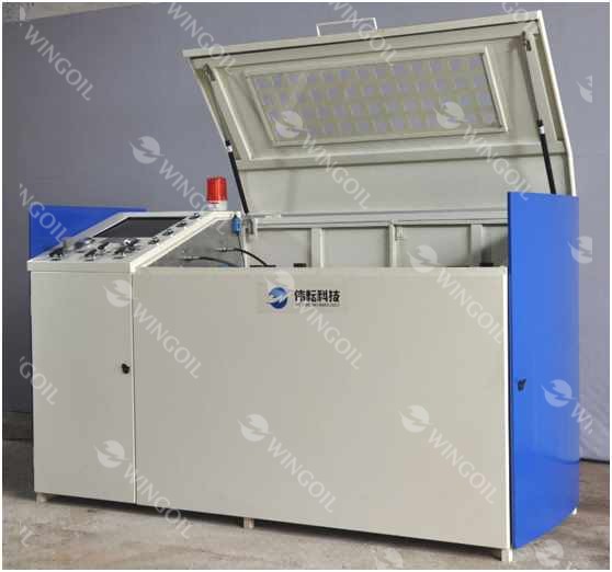
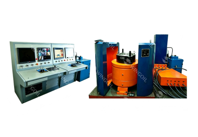
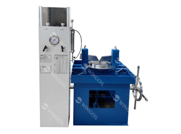
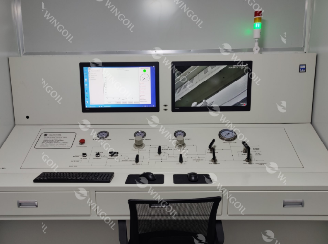
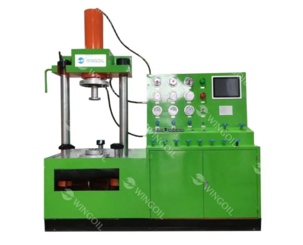
Wingoil BOP Control System: Professional Solution for High-Pressure Well Control Testing Safety
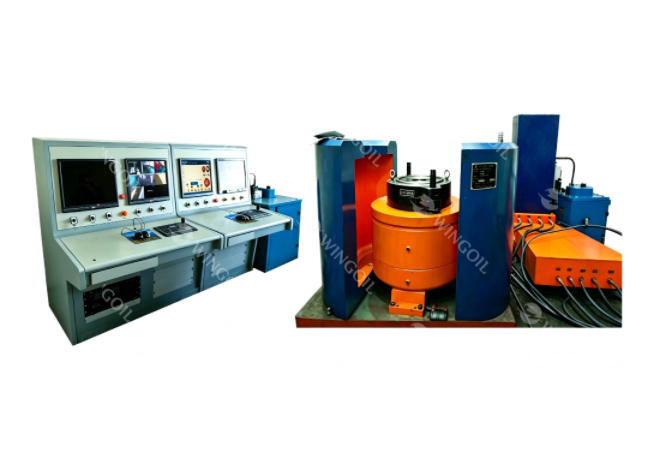
If you are looking for reliable BOP testing equipment, to meet stringent specifications such as API 53 and address safety risks in high-pressure testing, choosing a precise, stable, and safe testing system is essential. The Wingoil BOP Control System is specifically designed for hydrostatic strength and sealing performance testing of well control equipment and Christmas trees during factory acceptance, post-maintenance re-inspection, and routine field maintenance.
Core Advantages & Technical Features
Ultra-High Pressure & Precision Control: The machine is designed for the testing pressure from 1 MPa to 140 MPa (maximum designed pressure of 160 MPa / 23,200 psi). There can be up to 6 levels of pressure increment performed automatically with the deviation of ±0.5 MPa set as a goal.
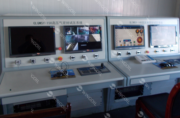
Human-Machine Separation & Multiple Explosion-Proof Measures: The human-machine separation safety design is used for high pressures. The whole controlling and electrical part satisfies hazardous zone explosion-proofing requirements. It is equipped with automatic overpressure stop, sound-light alarm, and manual/remote emergency pressure release devices.
Multi-Station Independent Automated Testing: Features fully automated pressurization, segmental pressure holding, and stepped pressure relief logic. Multiple stations can independently set parameters and hold pressure separately, greatly improving testing efficiency for multi-component assemblies.
Digital Traceability & Automated Reporting: Real-time collection of pressure data (measurement accuracy ≤0.5% F.S.), automatic generation of “pressure-time” curves, supporting one-click export of standardized PDF test reports complying with API specifications.
Key Specifications
| Parameter Item | Technical Specifications |
| Test Medium / Pressure Range | Ambient water, antifreeze / Low pressure 1 MPa – High pressure 140 MPa |
| Design Max Pressure (RWP) | 160 MPa (23,200 psi) |
| Control & Measurement Accuracy | Pressure measurement accuracy ≤0.5% F.S.;Target control deviation ±0.5MPa |
| Step Pressurization / Station Capacity | Supports up to 6-stage step pressurization; equipped with 50T hydraulic clamping tooling |
| Power & Operating Environment | 380V AC (50Hz), 11 KW; suitable for 0°C–45°C explosion-proof field environments |
Troubleshooting Common Pressure Drops of BOP
During high-pressure field testing, abnormal pressure fluctuations or continuous pressure drops are relatively common issues. Quickly and accurately diagnosing the causes of failure can significantly reduce Non-Productive Time (NPT) and ensure compliant and efficient testing.
1. Trapped Air
Phenomenon & Mechanism: In cases where water is filled and pressurized, the occurrence is characterized by a relatively low increase in pressure or even a decrease in pressure immediately after the cessation of pumping until equilibrium is attained. This happens because of incomplete removal of air from the cavities in the systems or pipelines as a result of the highly compressible nature of air.
Corrective Action: It is necessary for depressurization to occur, and the vent valve that is at the highest point within the system should be opened. Air should be completely removed from the system by continuous injection of medium until the vent line is discharging consistently without bubbles.
2. Test Plug / Testing Cup Seal Failure
Phenomenon & Mechanism: During pressurization, the pressure shows a continuous and steady downward trend. Although no external water leakage is observed outside the BOP, liquid flows out on the casing side or lower flow passage. This phenomenon is mostly caused by damaged, rolled, or long-term worn O-rings and composite seals of the test plug or testing cup during running-in, leading to fluid communication across the isolation interface under high pressure.
Corrective Action: The system should be depressurized and brought under control, followed by pulling out the test plug/testing cup. The seals of rubber and the metal sealing surfaces need to be checked carefully. In case there is any scratch, wear and tear, or extrusion damage, new seals of the same specification are required to be installed and the surfaces cleaned before retest.
3. Thermal Expansion / Contraction Effect
Phenomenon & Mechanism: When there is a significant temperature difference between the injected test water medium and the BOP body/wellhead ambient temperature, the liquid within the closed high-pressure cavity will undergo thermal expansion or contraction due to temperature conduction, causing the pressure gauge to show a false “continuous pressure drop” or “slight pressure rise”.
Corrective Action: Use a water source as close to the ambient temperature as possible before testing. If the temperature difference is objective, allow the system to stand and stabilize at the predetermined pressure for 2–3 minutes. Once the heat exchange tends to balance and the pressure curve stabilizes, officially start timing and recording test data.
FAQs about BOP Hydrostatic Pressure Testing
Q1: Can BOP hydrostatic pressure testing completely replace pneumatic testing?
It cannot completely replace it, but hydrostatic testing is the foundation. Hydrostatic testing is primarily used to verify structural strength and high-pressure sealing. Under certain specific specifications (such as gas wells with high gas-tightness requirements), low-pressure or high-pressure nitrogen gas tightness tests are added after the hydrostatic test passes; however, the hydrostatic test must be passed prior to gas-tightness testing.
Q2: What is the qualified hold time for a BOP hydrostatic pressure test?
According to API Standard 53, for surface BOP systems, the hold time for both low-pressure and high-pressure tests must be no less than 5 minutes. During the hold time, the pressure recording curve must remain stable without leakage or significant pressure drop.
Q3: Why does the pressure drop slightly during pressurization? Is it necessarily a water leak?
Not necessarily. In addition to system leakage, the compression of residual trace gases in the liquid, micro-expansion of high-pressure hoses, or temperature differences between the high-pressure medium and the external environment (thermal expansion/contraction) can all cause a slight pressure drop in the initial stage. Therefore, codes usually allow a short period of “pressure stabilization balancing” before officially starting the timing scale.
Conclusion
The standardized hydrostatic pressure testing on the BOP system is not only an essential process to comply with API 53 and API 16A regulations but also a critical approach to guarantee the safety of drilling operations and avoid any blowouts. The use of accurate pneumatic high-pressure hydrostatic test pumps and digital data acquisition systems will help to increase the testing efficiency while making sure that all the testing data is authentic. In case you require designing a hydrostatic pressure testing system for BOPs and other wellhead equipment, you may contact Wingoil with your project specifications.
Related Articles